How to Terminate 4.3-10 Connector on LMR Cable
Hey there, 4.3-10 Connector
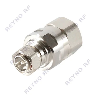
If you’re reading this, chances are you’re working with 4.3-10 connectors and LMR (Low Loss Microwave Radio) cables – maybe you’re a technician building a new wireless network, a field engineer troubleshooting a connection, or even someone just starting out in the RF (Radio Frequency) industry. As a supplier who’s spent years supporting folks with these components, I’ve seen both the perfect terminations that make networks sing and the small mistakes that turn into big signal loss headaches. Today, I want to walk you through exactly how to terminate a 4.3-10 connector on LMR cable the right way – no fancy tricks, just practical, step-by-step advice that comes from actually doing this in the lab and out in the field.
First, let’s talk about why the 4.3-10 connector and LMR cable pair matters. The 4.3-10 is a workhorse in modern wireless infrastructure – 5G, small cells, distributed antenna systems (DAS), you name it. It’s got a 50-ohm impedance, which matches most RF cables, and it’s designed to handle high power while keeping signal loss super low. LMR cables, especially LMR-400, LMR-240, and LMR-600, are the go-to for low-loss applications because their solid copper conductors and foam dielectric cut down on that frustrating signal bleed. But here’s the thing: even the best connector and cable won’t work right if the termination is botched. I’ve had customers come to me with “broken” connectors only to find they skipped a simple step when stripping the cable. So let’s make sure you don’t make those same missteps.
Before we dive into the process, let’s gather your tools. You don’t need a whole workshop – just the essentials. First, you’ll need a quality cable stripper specifically made for LMR cables. Regular wire strippers will tear the foam dielectric or nick the center conductor, which ruins everything. I recommend a stripper that’s calibrated for your LMR type – LMR-400 uses a different strip length than LMR-240, for example. Next, a sharp utility knife or a deburring tool to clean up the edges after stripping. You’ll need a torque wrench (set to the manufacturer’s specified value – usually around 25 in-lbs for 4.3-10 connectors) and, of course, your 4.3-10 connector and LMR cable. A pair of tweezers can be helpful for handling small parts, and maybe a magnifying glass if your eyes aren’t as sharp as they used to be – those small center conductors can be tricky. Also, have a clean cloth and some isopropyl alcohol handy to wipe away any debris.
Now, let’s get to the actual termination steps. I’ll use LMR-400 as our example because it’s the most common, but the basics apply to other LMR sizes too.
Step 1: Measure and Mark the Cable. First, check your 4.3-10 connector’s installation guide – this is non-negotiable. Every connector has a specific strip length, and it’s printed right on the datasheet. For LMR-400, that’s typically about 1.25 inches (31.75 mm) from the end of the cable. Take your cable, hold it up to the marked strip length line, and use a permanent marker to make a clear mark. Don’t rush this – a wrong mark here means you’ll either cut too much dielectric (which causes signal loss) or not enough (so the connector won’t seat properly).
Step 2: Strip the Cable. Attach the LMR stripper to the marked point, making sure the blades are set to the right depth. You want to cut through the outer jacket and the braid, but not nick the center conductor. Twist the stripper around the cable a few times, then gently pull off the outer jacket – you’ll see the braid and the foam dielectric underneath. Next, use the stripper’s inner blade to trim the braid back to about 0.5 inches (12.7 mm) from the jacket end. Be careful here – if you cut the braid too short, it won’t make a good ground connection. If you leave too much, it might touch the center conductor and cause a short circuit. Finally, trim the foam dielectric back to the mark you made earlier, making sure not to damage the center conductor.
Step 3: Prepare the Center Conductor. The center conductor needs to be clean, straight, and free of any burrs. Run your deburring tool along the end of the center conductor to smooth out any rough spots – a jagged center conductor will reflect signals, increasing insertion loss. Wipe the center conductor and the exposed dielectric with the isopropyl alcohol and cloth to remove any shavings or residue. Even a tiny piece of metal on the dielectric can cause a arc or signal loss down the line.
Step 4: Insert the Cable into the Connector. Now, take your 4.3-10 connector – most have three parts: the outer body, the center pin, and the clamp that holds the braid. Slide the clamp over the braid, then align the center conductor with the hole in the center pin. Gently push the center conductor into the pin until it clicks – you should feel a slight resistance, and it should be fully seated. Make sure the braid is spread evenly around the clamp, not bunched up on one side. If the braid is bunched, it won’t make full contact with the connector’s outer body, which is bad for shielding.
Step 5: Crimp or Torque the Connector. Wait – some 4.3-10 connectors are crimp-type, others are torque-style. For many of the newer designs, you’ll use a torque wrench to tighten the locking nut to the specified value. This is critical – overtightening can crack the dielectric, while undertightening will cause the connector to come loose over time. For crimp-type connectors, use a hydraulic crimping tool made for your LMR size, and make sure the crimp is uniform around the connector body. I always tell customers: when in doubt, check the manufacturer’s specs. We provide a full installation manual with every connector we sell, and it’s there for a reason.
Step 6: Inspect the Termination. This is the step most people skip, but it’s the one that catches 90% of mistakes. Take a close look at the termination: the center conductor should be straight, with no nicks. The braid should be evenly spread, not overlapping or gaping. The connector body should be flush against the cable jacket, with no gaps. If you see a problem – like a bent center conductor or a frayed braid – cut it off and start over. A bad termination might work temporarily, but it will cause signal issues, dropped calls, or even network outages in the long run.
Now, let’s talk about common mistakes I see all the time, especially from technicians new to 4.3-10 connectors. First, using a generic cable stripper. I’ve had a customer bring in a cable where someone used a regular wire stripper, and it not only nicked the center conductor but also tore the foam dielectric, leading to a 10dB signal loss – that’s enough to make a 5G cell tower barely cover a block. Second, not cleaning the cable before assembly. Dirt or oil on the dielectric can create a signal reflection, so a quick wipe with alcohol is worth the extra 30 seconds. Third, ignoring torque specs. I’ve seen guys tighten a 4.3-10 with a pair of pliers, and when they tested it, the impedance was off by a whole ohm – that might not seem like much, but in RF terms, it’s a big deal. Fourth, rushing the inspection. A minute spent looking at the termination can save hours of troubleshooting later.
If you’re working in the field, there are a few extra tips to keep in mind. Temperature extremes can affect terminations – if you’re installing in a cold climate, make sure your connector and cable are at room temperature before terminating, because cold can make the plastic parts brittle. In hot weather, don’t leave your tools in the sun – heat can warp the stripper blades. Also, always carry a spare connector and a small tool kit with you out in the field. I’ve had to make emergency terminations on job sites, and having a backup is a lifesaver.
Testing your termination is just as important as making it. Once you’re done, use an RF cable analyzer to check insertion loss, return loss, and impedance. A good 4.3-10 termination should have insertion loss less than 0.1dB at 2GHz, and return loss better than 25dB. If it doesn’t pass that, go back and inspect again – chances are you missed a small step. We actually recommend that all our customers test every termination before installing it, because it’s way easier to fix a problem on the bench than up a cell tower.
As a connector supplier, I hear all the time that technicians want connectors that are easy to terminate, reliable, and don’t break the bank. That’s why we focus on making 4.3-10 connectors that are designed for LMR cables – with clear mark lines, calibrated parts, and consistent torque points. But even the best connector won’t do the work for you. The key is taking your time, following the steps exactly, and inspecting every single termination.
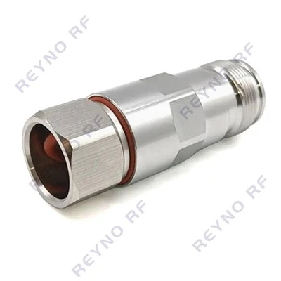
If you’re currently working on a project and need the right 4.3-10 connectors for your LMR cables, or if you have questions about a specific installation, don’t hesitate to reach out. Our team has years of experience in RF connectivity, and we’re here to help you get the job done right – whether you’re a small business installing a DAS or a large carrier building out 5G. We can walk you through custom solutions, provide datasheets with exact strip lengths, and even share field tips we’ve learned over the years.
N RF Connector Don’t let a botched termination ruin your network. Take the time to do it right, and you’ll have a connection that’s reliable, low-loss, and built to last.
References
- “4.3-10 Connector Installation Guide”, Johnson Aerospace & Defense, 2022.
- LMR Cable Technical Specifications, Times Microwave Systems, 2021.
- RF Connector Termination Best Practices, Wireless Infrastructure Association, 2023.
- “Insertion and Return Loss Measurements for 4.3-10 Connectors”, IEEE Transactions on Microwave Theory and Techniques, Vol. 70, No. 3, 2022.
Zhenjiang Leiluo Electronic Co., Ltd.
Zhenjiang Leiluo Electronic Co., Ltd. is one of the most professional 4.3-10 connector manufacturers and suppliers in China. We have world-leading production equipment and strong manufacturing capabilities. Please feel free to buy advanced 4.3-10 connector for sale here and get quotation from our factory. Customized orders are welcome.
Address: No.21 Houxiang Industrial Road, Danbei Town, Danyang City, Jiangsu Province
E-mail: wenvy@rfleiluo.com
WebSite: https://www.rfreyno.com/
