Hey everyone, let’s cut through the noise and get real about load switches—because if you’re designing circuits, messing up this part can turn a smooth prototype into a headache (trust me, I’ve seen it). For those who don’t know me, I’m with a load switch supplier, so I live and breathe these little power workhorses all day. Today, we’re talking about how to actually connect one right, no fancy jargon that makes your eyes glaze over. Let’s dive in. Load Switch
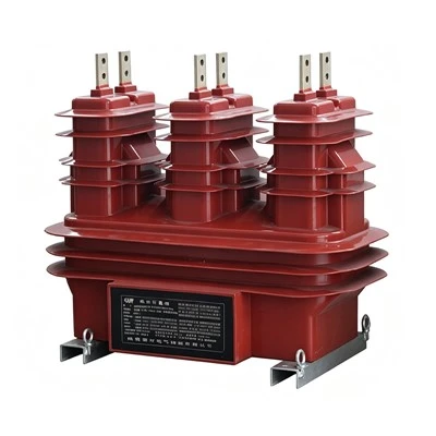
First, let’s get the basics straight: what even is a load switch, and why should you care? It’s not some random power toggle. A load switch is a tiny, controlled switch that turns power on or off to specific parts of your circuit—think of it as a smarter alternative to a manual toggle or a regular transistor. You use it to save battery (super important for wearables or portable gear), isolate components when they’re not in use, or even protect sensitive parts from surges. The key here is “controlled”: it turns on/off via a tiny signal (usually from a microcontroller, a button, or another control circuit), not just flipping a wire. If you skip proper connection, though, you’re leaving performance on the table or even risking damage to your parts.
Let’s start with the most critical first step: picking the right load switch for your circuit. Wait, I know you’re eager to wire it up, but trust me—skipping this step wastes so much time later. What do you need to check first? The voltage and current your load is drawing. If your load is a 3A LED strip and you grab a load switch rated for 1A, that thing’s gonna overheat and die fast. Next, what’s your control signal voltage? Most load switches work with 1.8V, 3.3V, or 5V logic, so if your microcontroller only spits out 1.8V, don’t get a switch that needs 5V to turn on. Also, think about any extra features you might need: do you need inrush current protection? (That’s when big power draws when a load first turns on—like a motor kicking on.) Or soft-start, so the power ramps up instead of jolting? For the record, we stock load switches with all these features, so if you’re stuck, just reach out.
Now, let’s get to the actual wiring. I’m gonna break this down step by step, like I’m showing a buddy in my workshop—no fancy schematics you have to squint at, just plain talk. First, gather your parts: the load switch itself, your power source (battery, wall adapter, whatever), your load (the thing you’re powering—LED, motor, sensor), some wires, a breadboard if you’re prototyping, and a multimeter to test (you’ll want that).
Step 1: Map the pins. Every load switch has standard pins, even if brand names change. Let’s list the ones you’ll always see: VIN, GND, SW, and EN. VIN is your power input—this is where you hook up the positive lead from your power source. GND is ground, so that’s the negative of your power source, and also the ground for your circuit, so it needs to tie to all other grounds in your setup. SW is the switch pin—this is where your load connects. When the switch is on, power flows from VIN to SW, so that’s your path to the load. EN is the enable pin—this is the control pin, the one that tells the switch to turn on or off. That’s the one you connect to your microcontroller, button, or whatever is sending the on/off signal.
Wait, hold up—common mistake here: mixing up SW and VIN. I’ve had customers come back to us saying their switch isn’t working, and 9 times out of 10, they swapped those two. Don’t do that. Let’s make it simple: VIN = power coming into the switch, SW = power going out to your load.
Step 2: Wire the power and ground first. Take your power source’s positive wire and connect it to the VIN pin on the load switch. Then take the negative wire of your power source and connect it to the GND pin of the load switch, and also connect that same GND to the ground of your microcontroller (if you’re using one) and your load. Ground is the common return path—if it’s not all tied together, weird stuff happens, like the switch not turning on when you send a signal.
Step 3: Connect the load to the SW pin. Take the positive lead of your load (the LED strip, motor, whatever) and hook that up to the SW pin on the load switch. Then take the negative lead of your load and connect that to the same ground bus you used for VIN and GND. Now, when the switch is on, power flows from VIN → SW → load → GND, and your load gets power. When it’s off, that path is broken, so the load gets nothing. Easy, right?
Step 4: Wire the enable pin—this is where the control happens. Most of the time, you’ll connect the EN pin to a GPIO (general purpose input/output) pin on your microcontroller. If your microcontroller puts out 3.3V, make sure your load switch is rated for 3.3V EN signal (most are these days). If you want the switch to always be on (no control needed), you can tie the EN pin directly to VIN—just make sure that’s allowed, some switches have a default off state, so check the datasheet. If you’re using a manual on/off switch instead of a microcontroller, you can wire a small pushbutton between EN and VIN: pressing the button connects EN to VIN, turning the switch on, and releasing it might turn it off, depending on if it’s latching or momentary.
Wait, another big thing: decoupling capacitors. I can’t stress this enough. Almost every load switch datasheet will tell you to add a 0.1µF ceramic capacitor across VIN and GND, and sometimes another one at SW and GND. Why? To filter out noise from the power source. If there’s a voltage spike or ripple, the capacitor absorbs it, so the switch doesn’t glitch on and off by itself, and your load doesn’t get damaged. Skipping this is a recipe for unreliable circuits—ask me how I know. I once had a customer’s drone prototype crash because they forgot the decoupling cap, the load switch was turning on/off randomly during flight. Oops.
Now, let’s talk about special cases, because not all circuits are the same. First, low-voltage, high-current loads. If you’re powering something like a 12V motor that draws 5A, you can’t just connect a tiny load switch meant for phones. You’ll need a load switch with a high current rating, and sometimes you’ll need a heat sink too—higher current means more heat, so the switch can get hot enough to fail if it’s not dissipated. If you’re not sure what rating you need, shoot us a message, we can help you spec it.
Then there’s inrush current. Like I mentioned earlier, when you turn on a motor or a big LED array, the current spikes way higher than the normal operating current—sometimes 5x or 10x. If your load switch can’t handle that inrush, it’ll blow. Look for load switches with built-in inrush current limiting, or add a soft-start circuit (some switches have that built right in) so the power ramps up slowly instead of spiking. We have a line of load switches specifically for high inrush applications, perfect for motors and industrial gear.
What about reverse polarity protection? If your circuit could accidentally have the power wires swapped (I’ve done that a hundred times when prototyping), a load switch with built-in reverse polarity protection will save your parts. It blocks current from flowing backward if you hook VIN and GND up wrong, so you don’t have to reflow a bunch of boards because you messed up a wire. That’s a lifesaver for prototyping, trust me.
Now, let’s walk through a quick example to make this concrete. Let’s say we’re making a portable IoT sensor that runs on a 3.7V LiPo battery. The main load is a Bluetooth module that draws up to 1A when transmitting, and the microcontroller draws 10mA at idle. We want to turn the Bluetooth module off when it’s not in use to save battery. Here’s how we’d wire it:
- Pick a load switch: something rated for 3.7V, 1.5A (to cover the 1A Bluetooth draw plus headroom), with EN rated for 3.3V (since our microcontroller is 3.3V), and a built-in decoupling cap, or we’ll add our own.
- Connect VIN of the load switch to the positive terminal of the LiPo battery.
- Connect GND of the load switch to the battery’s negative terminal, and also to the microcontroller’s ground pin.
- Connect the Bluetooth module’s positive wire to the SW pin of the load switch, and its negative wire to the ground bus.
- Connect the EN pin of the load switch to a GPIO pin on the microcontroller. When the microcontroller pulls that GPIO high (3.3V), the load switch turns on, powering the Bluetooth module. When it pulls it low, the switch turns off, saving battery.
- Add a 0.1µF ceramic capacitor between VIN and GND of the load switch to filter noise.
That’s it. Simple, and it’ll work every time if you don’t skip the steps.
Now, common mistakes to avoid, because I see these all the time:
- Forgetting decoupling caps: like I said earlier, this is the #1 reason load switches act weird. Even if the datasheet says you don’t need it, add it. It takes 2 seconds and saves hours of troubleshooting.
- Not matching the switch rating to your load: a 1A switch on a 2A load is a fire hazard, basically. Always derate by 20-30% too—if your load draws 1A, get a switch rated for 1.25A or more. That gives you headroom for spikes and aging parts.
- Mixing up EN and SW pins: it’s easy to do, especially if you’re in a hurry. Double-check the datasheet for your specific switch—pins can vary a tiny bit between brands, even if they’re standard.
- No ground connection for EN: if your EN pin isn’t tied to ground when it’s low, it can float, and the switch will turn on randomly. Always make sure when the control signal is low, EN is connected to ground.
- Ignoring thermal concerns: high current loads make the load switch heat up. If your switch is getting too hot to touch, add a heat sink or derate it more. Running it too hot shortens its life, sometimes to months instead of years.
Wait, what about if you’re doing surface-mount (SMD) instead of through-hole? Same basic logic, just the pins are on the bottom of the package. Just follow the datasheet’s layout guidelines closely—SMD circuits are way more sensitive to bad layout, like too-long traces or not enough space for the ground plane. If you’re new to SMD, most load switch manufacturers (including us) have reference schematics and layout guides, so use those. Don’t guess on SMD wiring—it’ll come back to bite you.
Another question I get all the time: can I use a load switch instead of a relay? Relays are bigger, slower, and wear out faster, especially when switching often. Load switches are solid-state, so they last longer, are smaller, and switch faster (microseconds vs milliseconds for relays). The only time you need a relay is if you’re switching very high voltage (like 120V AC) that most load switches can’t handle, or if you need electrical isolation between the control circuit and the load. For low-voltage DC circuits, load switches are almost always better. If you’re wondering if a load switch works for your specific application, just ask—we’re happy to help.
Now, a quick test to make sure you wired it right. Once you have it connected, power everything on. Use a multimeter set to voltage mode, put the red probe on the SW pin, black on GND. If the switch is on, you should read almost the same voltage as VIN—like 3.7V if your power source is 3.7V. If it’s off, you should read 0V (or a tiny voltage, like 0.1V, if it’s a good switch). If that’s not happening, go back and check your connections: is VIN connected? Is EN getting the right signal? Is ground all tied together? 9 times out of 10, it’s a loose wire or a swapped pin.
At the end of the day, connecting a load switch isn’t rocket science, but it’s easy to cut corners and mess things up. The most important things are: pick the right switch for your load, follow the pinout exactly, add decoupling caps, test before you put it into a final design, and double-check all connections.
If you’re working on a new project and aren’t sure which load switch to get, or you’ve wired one up and it’s not working, hit us up. We’ve got a huge range of load switches for every application—from tiny wearables to industrial equipment—and our team is here to help you spec, prototype, and get the right part fast. No runaround, no hidden hoops, just solid parts and real support. Whether you’re a hobbyist messing around in your garage or a big OEM designing a new product, we’re here to help you get your circuits right.
Now, a quick note on references, for anyone who wants to dive deeper into the technical stuff.
- National Semiconductor (now Texas Instruments) LM3489 Datasheet – Load Switch Basics and Application Notes
- ON Semiconductor NCP4551 Datasheet – Inrush Current and Decoupling Cap Requirements
- Analog Devices Technical Article: Solid-State Load Switch Design for Battery-Powered Devices
High Voltage Disconnector That’s all for today. Next time you’re wiring a load switch, don’t stress—just take it step by step, avoid the mistakes we talked about, and it’ll work like a charm. Catch you next time.
Zhongtai Electric Power Technology Co., Ltd.
With abundant experience, we are one of the most professional load switch manufacturers and suppliers in China. We warmly welcome you to wholesale bulk customized load switch from our factory. If you have any enquiry about quotation, please feel free to email us.
Address: High-tech Industrial Park, Chongren County, Fuzhou City, Jiangxi Province (No. 261 Yingbin Avenue)
E-mail: info@zhongtaielectric.com
WebSite: https://www.zhongtaipower.com/
